
Fox Delta Analyzer Construction Notes
http://www.foxdelta.com/products/aaz-0914a.htm
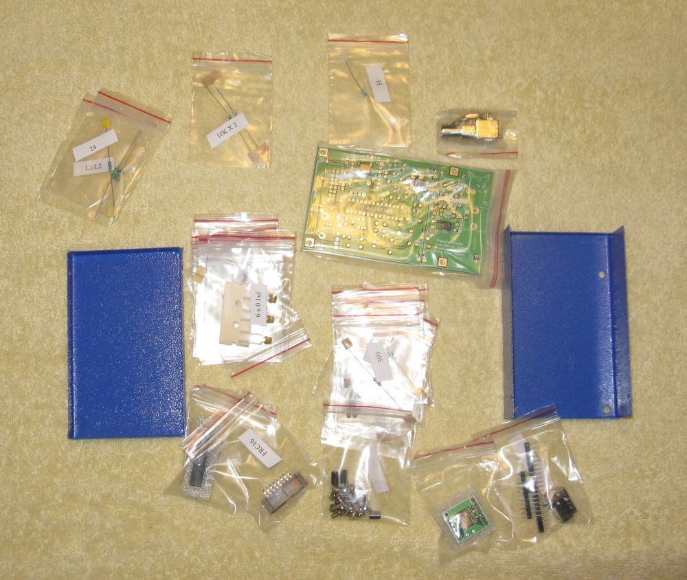
1. Shipping times. The CQ article ( http://www.foxdelta.com/products/infinity/CQ_Amateur_Radio_2014-08%20AAZ.pdf ) states that the reviewer received his in ten days, but I would not count on anything close to that - India is a long ways away! I ordered my analyzer on February 4, 2015, and received a shipping notice on February 6th that indicated a transit time of "15+" days and provided a tracking number. The link to the U.S. Postal Service shipping status webpage did not become active until March 17th when it entered the U.S. and I received it on March 21st. A friend ordered one after I ordered mine and received his before mine showed up, so go figure. Mine was received in good condition and was well packed in a sturdy box. The individual components were packed in small zip-lock bags that were labeled with the contents.
2. Construction preparation. I scanned the four page insert and printed a working copy to keep the original intact. I then inventoried them and taped the bags to a sheet of cardboard in the order they appeared in the parts list. I suggest that prior to construction that you read all of the information on the Fox Delta web page and links. You can download software and software manual from I2TZK's webpage at:
http://www.i2tzk.com/index.php?option=com_rokdownloads&view=folder&Itemid=55 . Note that there are a lot of webpages that show the completed circuit board, but not all show the current version, so I would be careful about using them as a go-by.
3. Construction. Assembling the kit is a matter of populating the board with the components. Note that the tantalum capacitors are polarized and marked with a tiny '+' that corresponds to a '+' on the board. I suggest that they be installed first. Note that the connections for PIC U2 are not polarized. I checked the photos of the unit and determined that the two holes in the U2 daughterboard should be toward the center of the board.
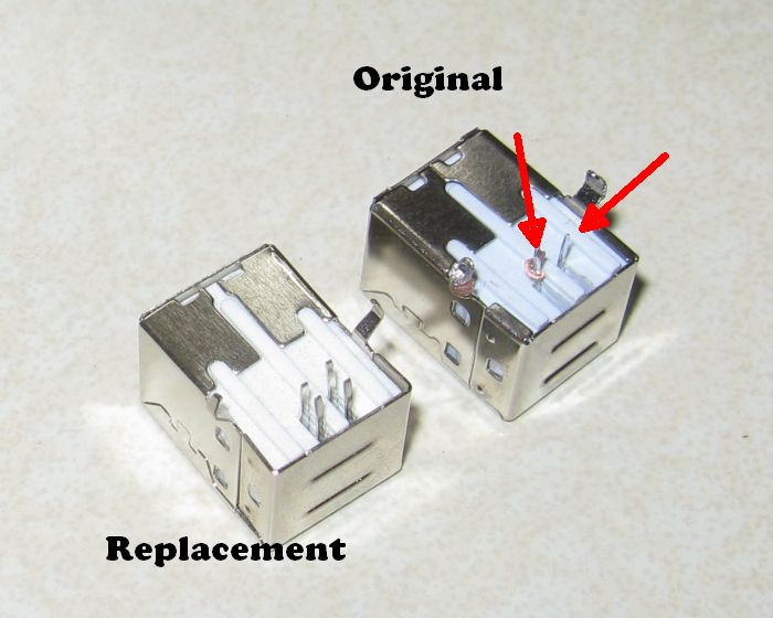
4. Power Up. I completed the board and attempted to power it up - no joy. I traced the USB circuit that provides power and determined that two of the leads were missing from the USB connector. I had noticed this when I soldered it to the board, but thought that it was part of the design and did not pay particular attention to it. I removed it and replaced it with a connector I purchased at Vetco. I installed the replacement connector and Windows 7 detected the analyzer and installed the appropriate drivers.
5. Software. The software does not install in your computer or change the registry. To use it, save it to your hard drive and create a link for the desktop. This is handy since you can run it from a memory stick if you wish. When you load the program it will detect the analyzer and ask you to calibrate. Calibration is done in two steps - open circuit and closed circuit. You must run both calibrations before the software will allow you to save the configuration.
6. Use. Note that the analyzer has a BNC antenna connector, so you will need an adapter if you are using other types of connectors. The software is straightforward and easy to learn.
If you have comments or questions please contact me at
![]()